Regulation framework
The Regulation framework provides 3 kinds of objects:
Inputto evaluate the actual state of the system (like the room temperature).Outputto perform an action on the system (like an heater).Loopto manage the regulation of the system via the PID parameters and a given setpoint (like the target temperature for the room).
For regulation purposes only the Loop object has to be imported in the Bliss session.
The Input and Output associated to a Loop are accessed via Loop.input and Loop.output.
The regulation controller can be accessed with the .controller property (ex: Loop.controller).
The regulation process can be described by the following steps:
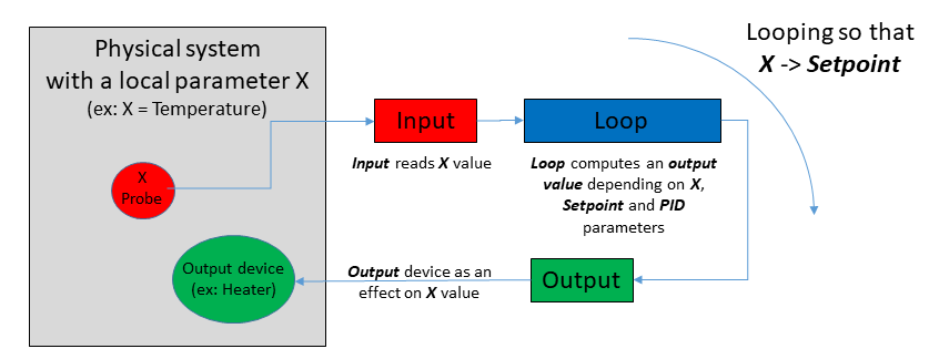
- Input reads the actual value of the processed variable (i.e. the physical parameter that is monitored by the regulation).
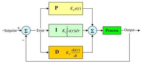
- Loop computes an output_value that depends on the actual value of the Input, the “distance” to the setpoint and the PID parameters.
- The output_value is sent to the Output. The output device has an effect on the system and modifies the value of the processed variable.
- back to step 1) and loop forever so that the processed value reaches the setpoint value and stays stable around that value (deadband).
See Interacting with the Loop object for further details about the usage of the Loop object within a Bliss session.
Configure a regulation hardware
The hardware regulation case corresponds to the situation, where a regulation
hardware exists and the regulation input and output devices are connected to
that hardware (like a lakeshore controller with temperature probes and heaters).
A controller can declare multiple inputs, outputs and loops. But one loop is always associated to one input and one output.
The loops, inputs and outputs linked to that controller are declared within the configuration of the controller.
These objects are the ones that should be imported in a Bliss session, not the controller!
Input, Output and Loop objects will access the Controller class written for the equipment.
The regulation controller can be accessed via these object with the .controller property (ex: Loop.controller).
To define a new controller class based on the regulation framework for a new hardware, see Writing a custom controller for a regulation hardware.
YML file example
- class: LakeShore336
  module: temperature.lakeshore.lakeshore336
  plugin: regulation
  name: lakeshore336
  tcp:
     url: lakeshore336se2:7777
     eol: "\\r\\n"  #  EOL could have been modified through the hardware interface
  inputs:   # the section to declare Inputs
    - name: ls336_A     # one input
      channel: A
      unit: Kelvin
    - name: ls336_A_c   # another input, same hw channel but using Celsius
      channel: A
      unit: Celsius
    - name: ls336_A_su  # another input, same hw channel but using sensor unit
      channel: A
      unit: Sensor_unit

    - name: ls336_B     # another input, different hw channel
      channel: B
      unit: Kelvin
    - name: ls336_B_c
      channel: B
      unit: Celsius
    - name: ls336_B_su
      channel: B
      unit: Sensor_unit

  outputs:  # the section to declare Outputs
    - name: ls336o_1    # one output
      channel: 1
      unit: Kelvin
    - name: ls336o_2    # another output
      channel: 2
      unit: Kelvin

  ctrl_loops:
    - name: ls336l_1    # one loop
      input: $ls336_B   # a reference to one of the inputs above
      output: $ls336o_1 # a reference to one of the outputs above
      channel: 1
    - name: ls336l_2    # another loop
      input: $ls336_B   # a reference to another input from above
      output: $ls336o_2 # a reference to another output from above
      channel: 2
In a bliss session import the Loop objects ls336l_1 or ls336l_2 but not the controller lakeshore336.
The controller can be accessed via Loop.controller (ex: ls336l_1.controller).
The Input and Output of the Loop can be accessed via Loop.input and Loop.output.
The Input and Output objects can also be imported in a Bliss session (for example when the regulation loop is not used and when the output is used in a direct control).
Configure a software regulation
Software regulation can be applied, where no existing hardware for regulation is available.
For example, it may be necessary to regulate a temperature by moving a cryostream with a motor (axis) or a beam position by
reading a diode and moving an axis.
ExternalInput, ExternalOutput encapsulate any object of the Bliss configuration into Input/Output and can be used by a SoftLoop.
SoftLoop runs a software PID algorithm using any pair of Input/Output.
External Input/Output
Any SamplingCounter can be directly
interfaced with an ExternalInput and any
Axis with a
ExternalOutput or ExternalInput.
- class: ExternalInput  # ExternalInput object to interface a counter as an input
  plugin: regulation    # use the regulation plugin for standard regulation classes
  name: myinput         # name for this input
  device: $mycnt        # ref. to a SamplingCounter (must exist in the config.)
  unit: volt            # (optional) unit for this input

- class: ExternalOutput # ExternalOutput object to interface an axis as an output
  plugin: regulation    # use the regulation plugin for standard regulation classes
  name: myoutput        # name for this output
  device: $robz         # reference to an axis (must exist in the config.)
  unit: mm              # (optional) unit for this output
  low_limit: -0.06      # (optional) low limit for a value applied to this output
  high_limit: 0.06      # (optional) high limit for a value applied to this output
  ramprate: 0.0         # (optional) usually no ramping for an axis as output
  mode: relative        # (optional) type of axis motion, in ['relative', 'absolute']
All other Bliss objects can be interfaced as a regulation input/output by
implementing a custom class inheriting from the ExternalInput or the
ExternalOutput classes.
- class: Chi2DiodeInput     # a custom object implemented by the user and
                            #  inheriting from the ExternalInput base class
  package: id26.controllers.chi2_diode_device  # where to find the object
                                               # class definition
  plugin: bliss             # custom object uses the standard bliss plugin
  name: chi2_diode_pos      # a name for this input
  device: $moco_chi2        # a reference to an object of the config that will
                            #  be interfaced as an input
  unit: log(finm/foutm)     # (optional) unit for this input
  signal_beam_limit: 1e-07     # (custom) extra attribute
  offset_finm: 1.70147994e-11  # (custom) extra attribute
  offset_foutm: 1.5094417e-11  # (custom) extra attribute
The custom Chi2DiodeInput is defined somewhere else (e.g ‘id26/controllers/chi2_diode_device.py’):
from bliss.common.regulation import ExternalInput

class Chi2DiodeInput(ExternalInput):

    def __init__(self, name, config): # (name, config) args to satisfy
        super().__init__(config)      #  bliss plugin requirements.

        # custom attributes
        self.offset_finm = config['offset_finm']
        self.offset_foutm = config['offset_foutm']
        self.signal_beam_limit = config['signal_beam_limit']
        self._last_value = 0

    def _get_chi2_counts(self):  # custom method
        # self.device is defined via the yml config (see 'device: $moco_chi2')
        count_chi2 = self.device.comm('?fbeam')
        count_finm = float(count_chi2.split()[0])
        count_foutm = float(count_chi2.split()[1])
        return count_finm, count_foutm

    def read(self):
        # MANDATORY: read() must be implemented (not implemented in the base class)
        count_finm, count_foutm = self._get_chi2_counts()

        d1 = count_finm - self.offset_finm
        d2 = count_foutm - self.offset_foutm

        if d1 > 0 and d2 > 0:
            self._last_value = (d1 - d2)/(d1+d2)

        return self._last_value

    def state(self):   # override base class implementation
        """ returns the input device state """
        return "READY"

    def allow_regulation(self): # override base class implementation
        """ this method inhibits the SoftLoop regulation if returning False """

        count_finm, count_foutm = self._get_chi2_counts()

        d1 = count_finm - self.offset_finm
        d2 = count_foutm - self.offset_foutm

        if d1 <= 0 or d2 <= 0:
            return False

        signal_beam = d1 + d2
        if signal_beam >= self.signal_beam_limit:
            return True
        else:
            return False
The YML configuration of the ExternalInput and ExternalOutput objects has a special keyword device to
make a reference to the Bliss object that should be interfaced. It can be accessed via the Input/Output object with .device.
For ExternalOutput interfacing an axis, a special keyword mode exist to define the kind of motion.
The mode value can be ‘relative’ or ‘absolute’. It can be accessed and modified with the ExternalOutput.mode property.
Default mode is ‘relative’.
Note
About Axis interfaced as ExternalOutput:
The relative motion mode is usually the most adapted.
The low_limit and the high_limit values should be chosen carefully.
In combination with the relative motion mode, users should use:
high_limit = - low_limit = maximum_step_size
The loop waits for the axis to reach its new position before doing the next PID iteration. Therefore, a small value for the maximum_step_size is preferred in order to perform the motion in a short delay, and then perform the next PID iteration as soon as possible.
The motion time should be smaller than 1/SoftLoop.sampling_frequency.
On the other hand if the maximum_step_size is too small, the expected effect of moving the axis is too weak and has a negligible effect on the system.
Start with a small value (like 2 times the axis tolerance) and increase slightly until you obtain significant effects on the system.
SoftLoop
To perform a regulation with the ExternalInput/ExternalOutput objects, users must declare a SoftLoop.
The SoftLoop object inherits from the Loop class and implements its own PID algorithm (using the simple_pid Python module).
Because there is no shared hardware controller for the regulation,
ExternalInput, ExternalOutput and SoftLoop have independent configurations
(i.e. not all declared under the same Controller class).
Inside the SoftLoop configuration section, there are references ($) to the
input and output objects that should be used for the regulation. Notice that a
SoftLoop can reference both the standard and the external types of Input/Output
objects.
YML file example
-   class: SoftLoop           # a SoftLoop object
    plugin: regulation        # use the regulation plugin for standard regulation classes
    name: chi2_regul          # a name for this loop
    input: $chi2_diode_pos    # the Input object to be used
    output: $chi2_motor_pos   # the Output object to be used
    P: -25                    # positive or negative Kp 'switches the output direction'
    I: 0.0
    D: 0.0
    low_limit: -1.0           # low limit of the PID output range. Usually equal to 0 (absolute) or -1 (relative).
    high_limit: 1.0           # high limit of the PID output range. Usually equal to 1.
    frequency: 10.0           # frequency of the regulation loop evaluation
    deadband: 0.00025         # deadband width (like a tolerance for the setpoint)
    deadband_time: 3.0        # minimum time (sec) to consider that the setpoint has been reached
    ramprate: 1               # ramprate is used as a 'speed' toward setpoint (ramprate=0 to apply setpoint immediately)
    wait_mode: deadband       # wait_move mode for the loop as a pseudo axis (loop.axis)
    max_attempts_before_failure: 5  # (optional) number of failed attempts to input.read or output.set_value
                                    # before stopping the loop (the default is 3)

-   class: Chi2DiodeInput     # A custom object implemented by the user and inheriting from the ExternalInput base class
    package: id26.controllers.chi2_diode_device  # where to find the object class definition
    plugin: bliss             # Custom object uses the standard bliss plugin
    name: chi2_diode_pos      # a name for this input
    device: $moco_chi2        # a reference to an object of the config that will be interfaced as an input
    unit: log(finm/foutm)     # (optional) a unit for this input
    signal_beam_limit: 1e-07     # (custom) extra attribute
    offset_finm: 1.70147994e-11  # (custom) extra attribute
    offset_foutm: 1.5094417e-11  # (custom) extra attribute


-   class: ExternalOutput   # a ExternalOutput object to interface an axis as an output
    plugin: regulation      # use the regulation plugin for standard regulation class
    name: chi2_motor_pos    # a name for this output
    device: $CHI2           # a reference to an axis name that must exist in the configuration
    unit: CHI2_position     # (optional) a unit for this output
    low_limit: -0.06        # (optional) the low limit for a value applied to this output
    high_limit: 0.06        # (optional) the high limit for a value applied to this output
    ramprate: 0.0           # (optional) usually no ramping for an axis as output
    mode: relative          # (optional) type of axis motion, in ['relative', 'absolute']
SoftLoop timeout resilience
You can make the SoftLoop more resilient to transitory communication errors like timeouts by increasing SoftLoop.max_attempts_before_failure. It can be specified in yml config like so:
max_attempts_before_failure: 100 # the loop will stop after 100 contiguous failed attempts to input.read or output.set_value
The default value for this property is 3.
Interacting with the Loop object
Type the name of the regulation loop in a Bliss shell to print information.
TEST_SESSION [3]: sample_regulation_new
Out [3]:
                  === Loop: sample_regulation_new ===
                  controller: Mockup
                  Input: thermo_sample_new @ 0.000 deg
                  output: heater_new @ 0.000 Volt
                  setpoint: 0.0 deg
                  ramp rate: 1.0 deg/s
                  ramping: False
                  kp: 0.5
                  ki: 0.2
                  kd: 0.0
Main methods:
Loop.setpoint: get/set the setpoint (target value). Starts the regulation (if not active already) and starts the ramping toward the setpoint using the actual ramp rate.Loop.ramprate: get/set the ramping rate. Set to zero to deactivate the ramping.Loop.is_ramping: return True until the loop is ramping to the setpoint.Loop.stop: stop the ramping (regulation will be maintained at current working setpoint).- (
Loop._stop_regulation): to stop the regulation process (not usual, be very careful)
Linked objects:
Loop.controller: return the controller object associated to the loop and shared with the input and output objects. ASoftLoopdoesn’t have a controller.Loop.input: return the Input object associated to the loop.Loop.output: return the Output object associated to the loop.
PID tunning methods:
Loop.kp: get/set the proportional coefficient of the PID regulation algorithm.Loop.ki: get/set the integral coefficient of the PID regulation algorithm.Loop.kd: get/set the derivative coefficient of the PID regulation algorithm.
Pseudo-axis methods:
Loop.axis: return the loop as a pseudo axis for scanning purpose.Loop.deadband: get/set the setpoint tolerance (half width of the band centred around setpoint value).Loop.is_in_deadband: return True if the input value is in the dead band.Loop.deadband_time: the minimum time to be ‘stabilized’ in the deadband (default 1s).-
Loop.wait_mode: this mode is used by the pseudo axis to determine if the axis is MOVING or READY.mode=1:
WaitMode.RAMP: READY as soon as theLoop.axishas finished ramping to the setpoint.mode=2:
WaitMode.DEADBAND: READY when the Input value is stabilized in thedeadbandfor a time longer thandeadband_time(default mode).
Counters:
A Loop is SamplingCounterController which as 3 sampling counters (Loop.counters):
- one for the setpoint value
- one for the input value (retrieved from loop.input)
- one for the output value (retrieved from loop.output)
Start and monitor the regulation loop
The regulation is started by setting the setpoint for the first time: loop.setpoint = value.
The Loop always uses ramping while moving to a new setpoint, unless ramprate==0.
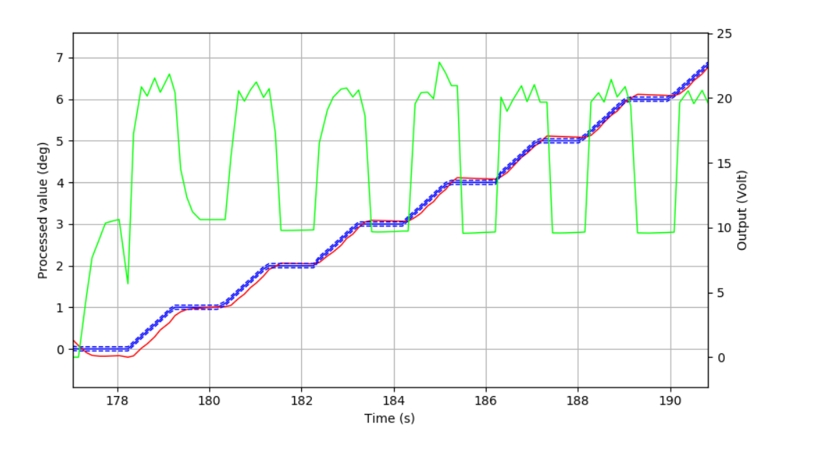
The regulation can be monitored through a plot in Flint using the command plt = loop.plot().
The plot can be closed by pressing the little cross on the top right corner of the plot tab in Flint.
The plot can be stopped and restarted using the commands plt.stop() and plot.start().
The refresh time of the plot can be modified with plt.sleep_time = 0.1.
TEST_SESSION [4]: loop.plot()
TEST_SESSION [5]: loop.setpoint=10
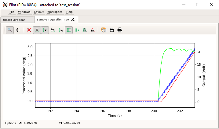
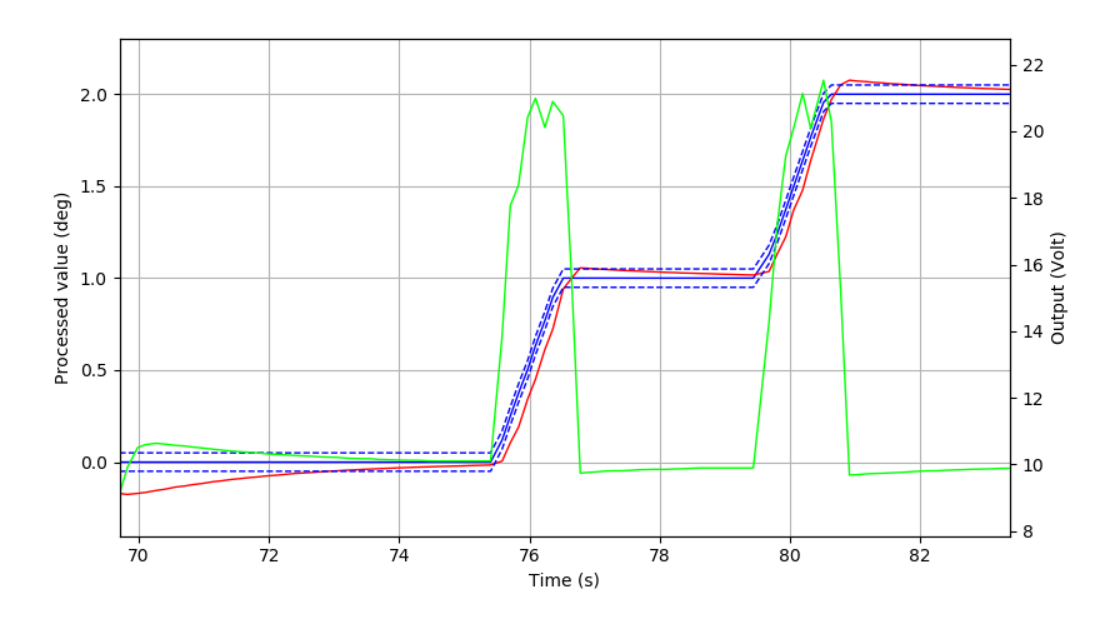
The left y-axis is the value read from the Input (red curve, processed value).
The right Y axis is the value read from the Output (green curve, Output).
The solid blue curve is the setpoint and the dashed blue curve is the deadband.
Ramping
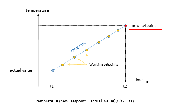
The Loop object has a ramping feature in order to control the progression toward the setpoint value.
When setting a new setpoint (loop.setpoint=10) the Loop always uses a ramp, unless ramprate==0.
While ramping, the Loop computes intermediate setpoints (workingsetpoints) matching the ramping slope.
The ramprate is a positive floating number and its unit is [input unit]/[sec].

The method Loop.is_ramping returns True if the Loop is currently ramping to the setpoint value.
It returns False if the ramping is disabled or if the workingsetpoint is equal to the setpoint (i.e. ramping has finished).
Note
Some regulation hardware may prevent the ramprate to be set to zero.
If the controller hardware doesn’t have the ramping feature, the Loop object will automatically provide a software ramping object (regulation.SoftRamp). The SoftLoop is using a SoftRamp. Use Loop.soft_ramp to access the object.
The Output object also has a ramping feature (same behaviour as the Loop soft_ramp).
If loop.output.ramprate != 0 then any new value sent to the output will use a ramp to reach that value.
The output ramping is useful when the hardware must be protected against brutal variations (like a high voltage output).
By, default the output ramprate is set to zero.
Note
While setting a new setpoint, some controllers will compute the ramp from the last setpoint or working setpoint instead of the current process value.
If the current process value is far from the working setpoint, this could lead to a unwanted ramp and dangerous overshoots.
To prevent this, by default, the framework forces the controller to compute the new ramp from actual process value by setting the setpoint to current process value just before applying the new setpoint asked by the user. This behavior can be deactivated by setting the loop attribute loop._force_ramping_from_current_pv to False.
This can be done in the loop YML configuration with the key ramp_from_pv.
    ctrl_loops:
        - name: ls336l_1    # one loop
        input: $ls336_B   # a reference to one of the inputs above
        output: $ls336o_1 # a reference to one of the outputs above
        channel: 1
        ramp_from_pv: False
Scanning
The Loop object has a special method Loop.axis that returns the loop as an Axis.
TEST_SESSION [3]: sample_regulation_new.axis.name
         Out [3]: 'sample_regulation_new_axis'
TEST_SESSION [4]: sample_regulation_new.axis
         Out [4]: AXIS:
                name (R): sample_regulation_new_axis
                unit (R): deg
                offset (R): 0.00000
                backlash (R): 0.00000
                sign (R): 1
                steps_per_unit (R): 1.00
                tolerance (R) (to check pos. before a move): 0.1
                limits (RW):    Low: -inf High: inf    (config Low: -inf High: inf)
                dial (RW): 0.00000
                position (RW): 0.00000
                state (R): READY (Axis is READY)
                acceleration: None
                velocity: None
            ERROR: Unable to get info from controller
            <bliss.controllers.motors.soft.SoftController object at 0x7fcecaf39f50>
            ENCODER:
                None
The axis is created once at the Loop initialization and is a standard Bliss Axis.
The axis name ({Loop.name}+’_axis’) is exported in the session and can by found in wa().
The axis tolerance parameter is set to the same value as the loop.deadband value.
The Loop.axis can be used like a motor in a scan and the Loop as counters.
TEST_SESSION [9]: ascan(loop.axis, 0, 10, 10, 1, loop)
Out [9]: Scan(number=252, name=ascan, path=/tmp/scans/test_session/data.h5)
Note
The Loop is a CounterController with 3 counters for the setpoint, input and output values.
Actually only the setpoint counter is owned by the Loop, the 2 others are respectively owned by
the loop.input and the loop.output objects.
However they are all retrieved by the Loop.counters method for convenience.
Therefore, lscnt() does not list all under the Loop.
Motion state and waiting mode
Behind the scene, while moving the Loop.axis to a new position,
the Loop sets a new setpoint and waits until it reaches the deadband around the new setpoint.
The axis is considered MOVING until the input value as reached the setpoint value.
If the Loop.wait_mode is:
WaitMode.RAMP(=1): the axis is READY as soon as the Loop has finished ramping to the setpoint.
WaitMode.DEADBAND(=2): the axis is READY when the Input value is stabilized within thedeadbandfor a time longer thandeadband_time(default mode).
SoftLoop specificities
With a standard Loop the PID algorithm is handled by the controller hardware and
the controller sends the new values directly to the output device.
With a SoftLoop the PID algorithm is handled by Bliss in a parallel task.
SoftLoop.sampling_frequency: adjust the update frequency of the PID algorithm.-
SoftLoop.pid_range: adjust the PID min/max range (output power range).[ 0, 1] for unidirectional ‘moves’ on the output (like heating more or less, [0% <=> 100%])
[-1, 1] for bidirectional ‘moves’ on the output (like heating/cooling or the moving direction for a motor, [-100% <=> +100%]).
Under the YML configuration of the
SoftLoopthe corresponding keywords arelow_limitandhigh_limit.- class: SoftLoop plugin: regulation name: chi2_regul input: $chi2_diode_pos output: $chi2_motor_pos low_limit: -1.0 # <-- low limit for the value computed by PID algo. Usually equal to 0 (absolute) or -1 (relative). high_limit: 1.0 # <-- high limit for the value computed by PID algo. Usually equal to 1.
PID range and Output limits
When the PID algorithm computes a value for the Output to reach the setpoint:
- the PID algorithm computes the output power value (restricted to
pid_range) - the output power value is rescaled using the min/max range defined on the Output (
Loop.output.limits) - the rescaled value is applied to the Output (
Loop.output.set_value)
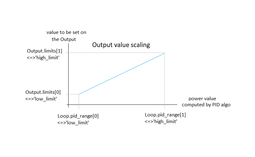
Note
The min/max range of the Output can be defined in its configuration with the keywords low_limit and high_limit.
Also can be accessed via the output object with Loop.output.limits.
Writing a custom controller for a regulation hardware
The custom controller class must inherit from the Regulation Controller class:
from bliss.controllers.regulator import Controller
The Controller class has pre-defined methods, which must be filled in the child class (the raise NotImplementedError methods). Other methods or attributes (custom methods or attributes) can be freely defined by the developer.
from bliss.controllers.regulator import Controller

class MyCustomController(Controller):

    # ------ init methods ------------------------

    def initialize_controller(self):

    def initialize_input(self, tinput):

    def initialize_output(self, toutput):

    def initialize_loop(self, tloop):

    # ------ get methods ------------------------

    def read_input(self, tinput):

    def read_output(self, toutput):

    def state_input(self, tinput):

    def state_output(self, toutput):

    # ------ PID methods ------------------------

    def set_kp(self, tloop, kp):

    def get_kp(self, tloop):

    def set_ki(self, tloop, ki):

    def get_ki(self, tloop):

    def set_kd(self, tloop, kd):

    def get_kd(self, tloop):

    def start_regulation(self, tloop):

    def stop_regulation(self, tloop):

    # ------ setpoint methods ------------------------

    def set_setpoint(self, tloop, sp, **kwargs):

    def get_setpoint(self, tloop):

    def get_working_setpoint(self, tloop):

    # ------ setpoint ramping methods (optional) ------------------------

    def start_ramp(self, tloop, sp, **kwargs):

    def stop_ramp(self, tloop):

    def is_ramping(self, tloop):

    def set_ramprate(self, tloop, rate):

    def get_ramprate(self, tloop):